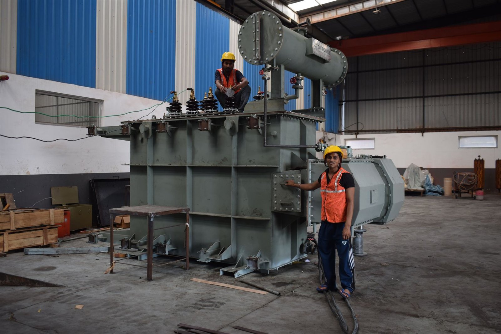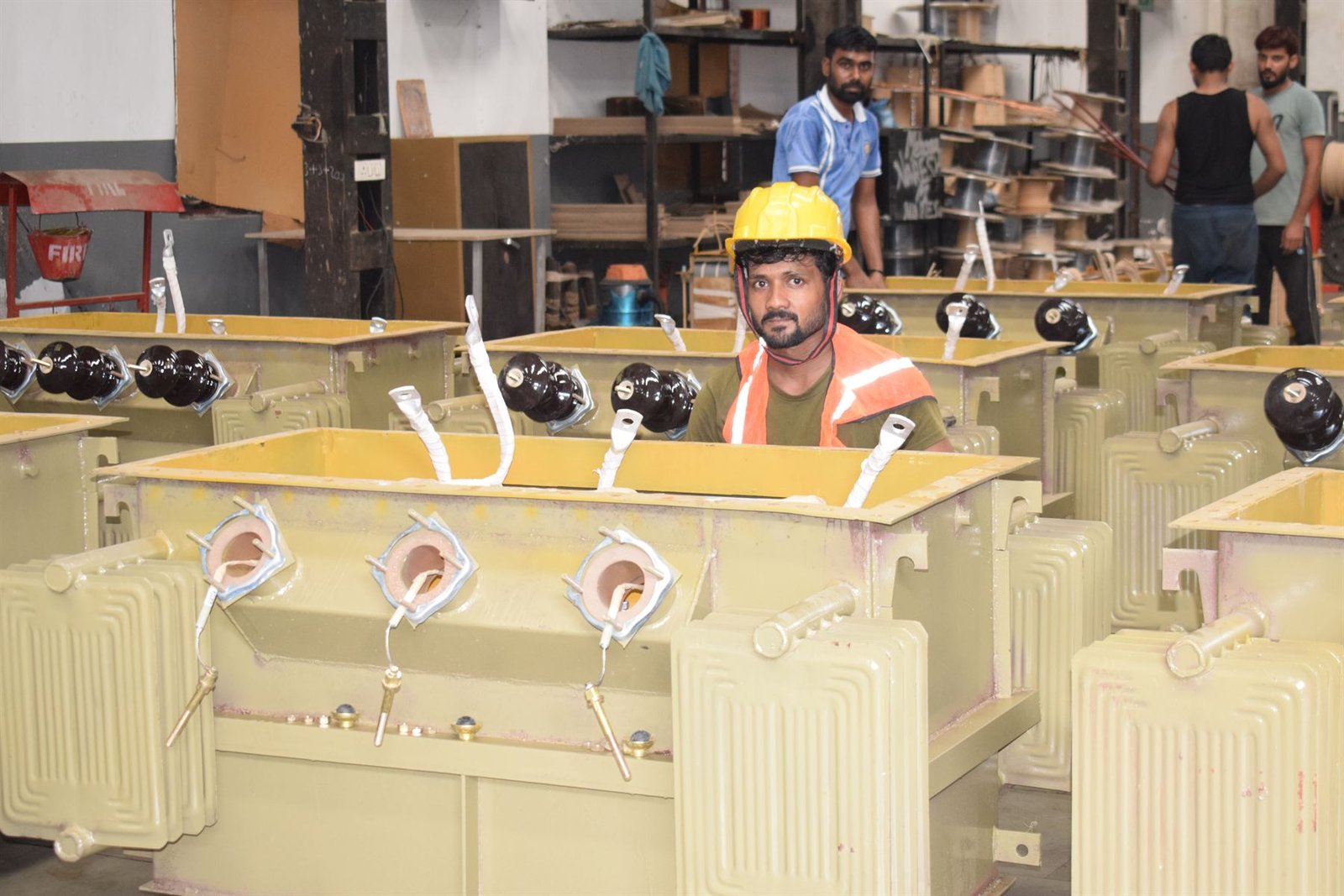
Solar developers are regularly offered a standard distribution transformer for an inverter application, usually at an attractive price. It will work, for a while. Here is what is actually different about a properly designed inverter duty transformer, and why each difference exists.
1. The LV voltage is not 433 V
A distribution transformer steps down to 433 V because that is what the network runs at. An inverter duty transformer steps up from whatever the inverter puts out — commonly 315, 380, 415, 480, 600, 690 or 800 V. The LV winding is designed around the inverter, not the grid.
2. The current is not sinusoidal
An inverter produces a current with meaningful harmonic content. Harmonic currents cause eddy-current heating in the windings that rises sharply with harmonic order, and a design that assumes a sine wave does not allow for it. Properly designed units use transposed or continuously-transposed conductors to break up those eddy paths, and de-rate the core flux density to leave headroom.
The design basis should be stated: typically a minimum 5% total harmonic distortion, with suppression of the third and fifth harmonics, and derating per IEEE C57.110. If you have the inverter OEM's harmonic spectrum, send it with the enquiry — it is the single most useful thing you can provide.
3. There are usually two secondaries
Most plants run two inverters into one transformer through a dual secondary, each LV winding rated at roughly half the total. The vector group that describes this is YNd11d11 or Dyn11yn11, not plain Dyn11.
4. The LV1–LV2 impedance is the number that matters
This is the one almost nobody publishes. The impedance between the two LV windings is what decouples the two inverters from each other. Set it too low and a disturbance on one inverter propagates straight into the other. The usual requirement is 11% or above, against roughly 7% from HV to each LV winding.
If a quotation for a dual-secondary transformer does not state the LV1–LV2 impedance, it has not been designed as an inverter duty unit. Ask for it before you compare prices.
5. Electrostatic shielding
A copper shield between the HV and LV windings limits the transfer of switching transients from the inverter into the network. On a dual-secondary unit there should be a separate shield for each LV winding, each brought out to its own 1.1 kV terminal so it can be earthed independently.
6. No-load loss matters more than you expect
This is the commercial argument, and it is the one most often missed. A solar plant generates for roughly half the hours in a year. For the other half the transformer sits energised and producing nothing — burning no-load loss around the clock.
On a distribution feeder, load loss usually dominates lifetime cost. On a solar step-up transformer, the weighting shifts hard towards no-load loss. That changes which design is actually cheapest to own, and it is why paying for a lower no-load loss core is more often justified here than almost anywhere else.
What to send with an enquiry
- Rated power and HV system voltage
- Inverter LV output voltage, and how many inverters per transformer
- The inverter's harmonic spectrum, or the OEM and model so we can obtain it
- Required LV1–LV2 impedance, if your consultant has specified one
- Vector group and tapping range
- Site ambient, altitude and pollution level
- Whether ester fluid is required for fire performance